Teaching Aims
Continuing on from the Shaft Design exercise, the Mechanism Design project looks to:
- provide awareness of mechanisms and their applications
- further practice design thinking, rationale capture and build on the feedback from the previous coursework
- apply system modelling tools to in prelimarny design scenarios
- practice your theoretical engineering knowledge in an unconstrained and unfamiliar environment
This site provides the resources you will need to work through thise exercise, although it is important to note that you are expected to do your own research to help you through the design problem.
To overcome this challenge, you will need to bring your engineering skill and knowledge that you have gained from all the modules you have completed so far.

The Design Exercise
This section presents the description of the exercise and can also be downloaded as a pdf.
Introduction
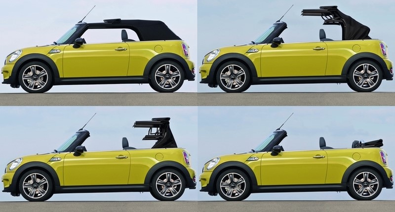
You will be working in pairs to design a mechanism that will open and close a roof for a convertible car as shown in Figure 2. This is an open-ended feasibility exercise with a high level of uncertainty. There are many ways that one could solve the problem. Your report should detail the:
- design process you have gone through
- assumptions made and their implications; and,
- justification for your design decisions.
To start, you will need to come up with a Product Design Specification (PDS) for the design of the mechanism. You will then come up with an initial set of concepts for a deployment mechanism and use the PDS to compare the concepts using the controlled convergence strategy. A decision should be made by week 20 as to which one you will be carrying forward for further iterations and preliminary design work. The PDS along with a diagram of your chosen concept will form a stage-gate submission at the end of week 20 (Friday 17th March, 2017).
After selecting your design, you will develop a dynamics model in Simulink that models the deployment and retraction of your mechanism. A description of the model should be presented within your report, which describes what calculations the simulink model is performing during each iteration. You should also describe how the motor & gearbox and has been modelled. The assumptions within the model should also be clearly articulated along with the likely impact they will have on the results that you will generate. Using this model, you will then trial a variety of motor, gearbox ratios and damping values to achieve a convertible roof with a smooth operation.
The gearbox ratio will then be used to form the initial requirement for your gearbox design. You will then evaluate the suitability of a multi-stage spur and helical gearbox. These will consist of gears of your choosing in order to generate the required ratio. Please note, your PDS should also cover requirements for your motor and gearbox.
The final aspect that you will cover is the creation of a general assembly of the gearbox arrangement. You are not required to select all the components in the gearbox although you could provide estimates for the shaft diameters and bearings given your experience from the previous exercise. The CAD model should have representative models of these components in order to demonstrate the arrangement.
Problem Details
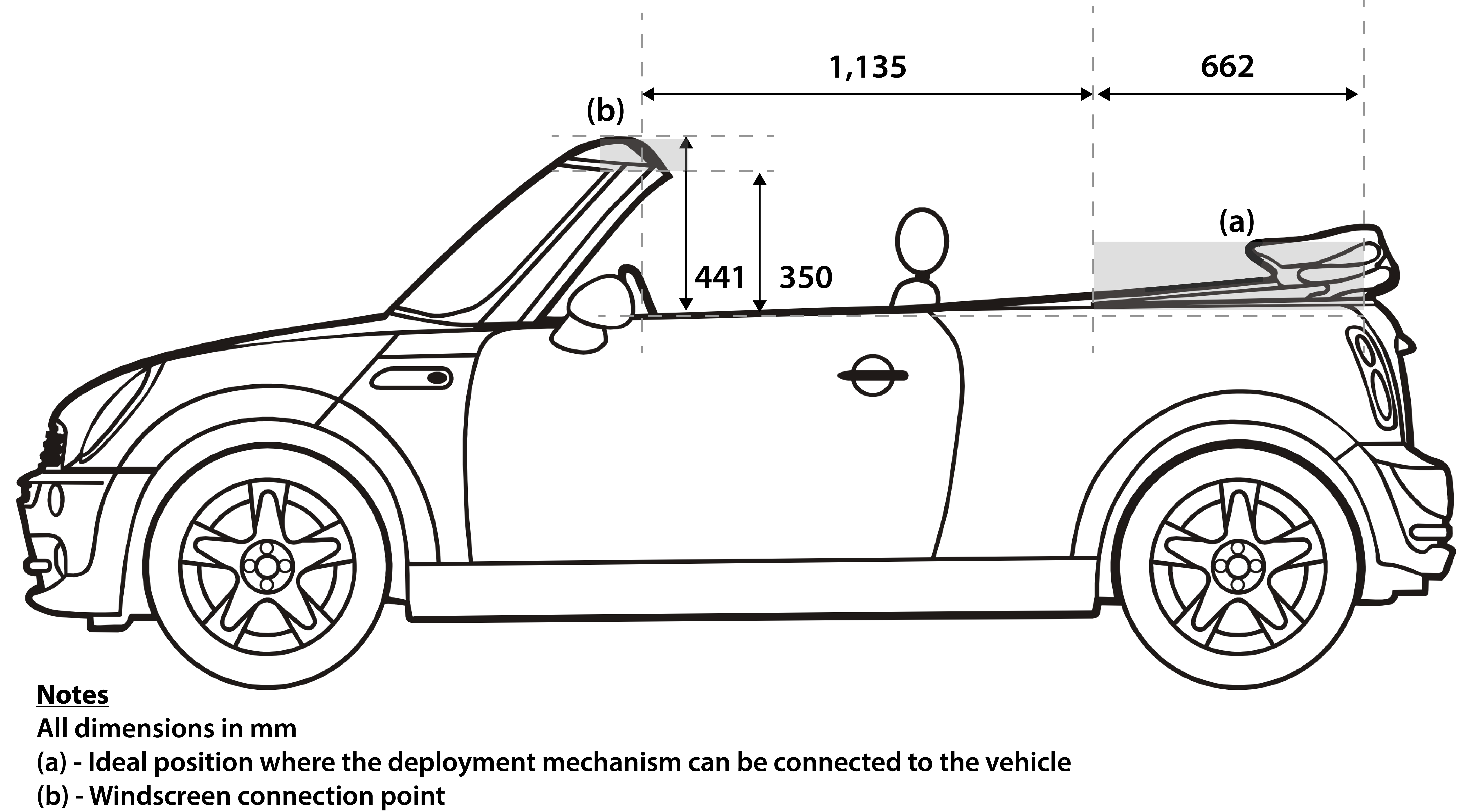
Figure 2 provides a drawing of the car that you will be designing for. The mechanism can be connected to the car within the boundary marked (a) and the mechanism has to extend to reach the windscreen (b). You do not have to worry about storing the mechanism when closed, as it will sit atop the main chassis as demonstrated in Figures 2 & 3. You should aim to collapse within the area (a) and extend to meet the windscreen within the region (b). You are not required to meet these values exactly but aim to get as close as possible.
To get you started, here are some example requirements that you should consider when forming your Product Requirement Specification. We do expect these points to be expanded upon and made quantifiable where possible.
- To have a reasonable deployment time.
- To minimise the space consumed when fully packed down.
- To maximise interior space when fully deployed.
- To be safe for operation near passengers.
- To minimise the energy required for deployment and retraction.
Submission
The exercise will be assessed through a stage-gate submission of your initial PDS and chosen concept at the mid-exercise stage-gate on blackboard (5%, Friday 17th March 2017) and a final design report that should also be submitted on blackboard as well as a hard copy submitted to the School Office by 3:30pm on 5th May 2017. A LaTeX template is provided for the report. The report should be no longer than 15 pages (excluding A3 submissions & reference list) and include the following (page guide and mark assignment in brackets):
- Title page (Title of the exercise, names & student numbers)
- Introduction (1 page)
- Product Design Specification (1 page, 10%)
- Concepts & Concept Selection (2 pages, 10%)
- Deployment Modelling (3 pages, 20%)
- Motor, Gear Ratio & Damping Selection (3 pages, 15%)
- Gearbox Design (3 pages, 20%)
- Solution Specification (1 page)
- Conclusion & References (1 page)
- Separate A3 pages of the (10%):
- Simulink Model; and,
- Gearbox Assembly Drawing.
Additional Notes
- 10% for the quality of report writing.
- The reference list may go beyond the 15 page limit.
Support & Timeline
As with the first exercise, supporting lectures are given on Tuesday afternoons and there is an expectation that you will work on the exercise ahead of the Tuesday morning sessions where there will staff available to provide formative feedback and support. Table 1 provides a summary of the time-line for the exercise.
| Teaching Week | Date | Time | Type | Content |
|---|---|---|---|---|
| 17 | Tuesday 21st February 2017 | 14:00-15:00 | Lecture | Introduction to the Feasibility Design Task |
| 19 | Tuesday 7th March 2017 | 9:00-13:00 | Tutorial | Form pairs, Exercise Familiarisation & Product Design Specification |
| 19 | Tuesday 7th March 2017 | 14:00-15:00 | Lecture | Product Design Specification, Concept Design & Selection |
| 20 | Tuesday 14th March 2017 | 9:00-13:00 | Tutorial | Concept Design & Selection |
| 20 | Tuesday 14th March 2017 | 14:00-15:00 | Lecture | Modelling the Deployment of the Mechanism 1 |
| 20 | Friday 17th March 2017 | 14:00-15:00 | Submission | PDS & Linkage Model of Selected Concept (Blackboard) |
| 21 | Tuesday 21st March 2017 | 9:00-13:00 | Tutorial | Deployment Modelling |
| 21 | Tuesday 21st March 2017 | 14:00-15:00 | Lecture | Modelling the Deployment of the Mechanism 2 |
| 22 | Tuesday 28th March 2017 | 9:00-13:00 | Tutorial | Deployment Modelling and Motor & Gear Ratio Selection |
| 22 | Tuesday 28th March 2017 | 14:00-15:00 | Lecture | Gearbox Design |
| Easter | ||||
| 23 | Tuesday 25th April 2017 | 14:00-15:00 | Tutorial | Gearbox Design |
| 24 | Tuesday 25th April 2017 | 14:00-15:00 | Lecture | General Assemblies & Submission Details |
| 24 | Tuesday 2nd May 2017 | 9:00-13:00 | Tutorial | Report Writing & Submission Details |
| 24 | Tuesday 2nd May 2017 | 14:00-15:00 | Lecture | Free |
| 24 | Friday 5th May 2017 | 15:30 | Submission | Feasibility Design Report Submission |
The Design Process
The design process you will follow consists of six main activties, which are:
- Product Design Specification
- Concept Generation
- Concept Selection
- Deployment Modelling
- Motor, Gear Ratio & Damping Selection
- Gearbox Design
This section provides a brief overview and guidance for each section. This is in addtion to the lectures and tutorial sessions. We strongly recommend that you utilise the tutorial sessions to help you through the exercise.
Product Design Specification
A Product Design Specification (PDS) contains all the requirements that your design needs to meet and is used to evaluate concepts as well as the performance of your design as you go through the design process. You will be expected to form your own PDS for this exercise
To do this, you are expected to research the capabilties of existing designs and environment in which this mechanism will operate in as well as use your own engineering knowledge on the likely factors that will affect its performance. Remember, it is important for you to be as complete as possible with the PDS eventhough you may not be assessing your concepts against some of the requirements that have been captured.
The format of the PDS should follow the format of the previous exercise and use the following headings:
| No. | Requirement | Must/Wish | Method of Assessment | Success Criteria | Will be assessed in this exercise |
|---|---|---|---|---|---|
| 1 | |||||
| 2 | |||||
| 3 |
It is important to note that the format we use in these design exercises is not the only method of presenting a PDS. A PDS could also come in the form of a report or use a more diagrammatic method such as a Weighted Objectives Tree.
Concept Generation
To generate your concepts, you will be provided with a lego construction kit that consisted of a number of bars and pins. Once you have generated a few potential solutions, you should use the Linkage software to create a digital version of the concepts. You can then use this model to evaluate the motion profile and take screenshots of your design for your report.
Here are a couple of tutorials from YouTube to help get you started with the software.
You should also be considering what you could calculate in order to compare the concepts. For example, you could provide estimates for the mass of each concept. These details should be included when discussing the concepts in your report.
Concept Selection
Looking back on your first year notes, your should recall that there are a number of techniques that one can use to evaluate their concepts. Examples include:
- Multi-criteria design analysis;
- Dot Sticking;
- Weighted Objectives Tree; and,
- Controlled Convergence.
Depending on your design problem, you may use one or more of these techniques in order to decide the concept to be taken forward.
In this exercise, you will be using the controlled convergence method for selecting the concept that you will take forward to the preliminary design phase. In controlled convergence, you take one of the concepts as the datum by which you compare you other concepts against. This comparison is made against the PDS that you have formed at the beginning of the exercise and for each requirement (where applicable) you assess whether the concept better, worse or the same as the datum. From this, you will getting a final score as to, which concept should be carried forward.
Deployment Modelling
Simulink is a block modelling environment that is widely used to model engineering systems. It has the capability to run complex multi-domain models using a range of solvers. Block modelling provides a great way to visualise the connections and flow of calculations within your system. A key advantage of creating a systems model is the ability to search the design sapce by varying the input design parameters.
In this task you will need to perform a few hand calculations in order to get an estimate of the torque required to get you mechanism moving. You should be able to do this with you knowledge of centre of masses and resistance due to gravity. From this you can select an intial motor (from Bosch) and the gear ratio for your gearbox (Guide: this will probably be in the range of 1:500-1:1000 ratio).
You will then create a systems model for your chosen design and the evaluating how the dynamic behaviour is affected by a change in the motor, gear ratio & damping parameters.
To support you in generating this model, you have two lectures dedicated to generating mechanisms within Simulank. These can also be found on YouTube. The demos showcases all the functionality that you will need but it up to you to generate the model for your system. Staff are available in the tutorials to help you with the logic of forming your model. Remember to record all the assumptions that have been made in generating the model and their impact on the results you will generate.
Templates for the models used in the videos are provided here.
A fully annotated A3 print out of your simulink model should be included in your report and clearly articulates what the model represents.
Motor, Gear Ratio & Damping Selection
Once you have your model, you can then start to investigate how changes in the motor, gear ratio and damping affect the performance of your mechanism (such as, deployment time). Graphs evaluating these parameters with respect to the performance of the mechanism are expected with multiple lines representing the different cases on the same graph.
After evaluating these parameters, you should arrive at an initial solution for the motor, gear ratio and damping that is required by your mechanism.

Gearbox Design
Now that you have calculated your gear ratio, you can begin to design the multi-stage gearbox. To do this, we will be following the design guidelines for the Mechanical Design Data Manual. You will have a lecture that will provide an overview of the gearbox design process. Your task is to evaluate both a spur and helical gear set for your mechanism. The following sections provide a summary of the guidelines is included in on this page for your reference.
Spur & Helical Gear Guidelines - from the Mechanical Design Data Manual
There are many types of gears used in engineering as set out in Australian Standard AS2075 - Glossary of Terms and Notations for Gears. Some of the types encountered include:
- spur
- helical
- double helical (herringbone)
- bevel
- hypoid
- worm
Two gears in mesh are called a gear pair. Normally gears mesh externally but sometimes the mesh may be internal, that is, one of the gears has the teeth cut internally. The smaller gear of a pair is called the pinion whereas the larger is called the wheel. In a pair of gears, the gear transmitting input torque and power is called the driver whereas the gear transmitting output torque and power is known as the driven. Normally in mechanical power transmission, the driver is the pinion so the wheel rotates at a slower speed than the pinion, that is, there is a reduction in speed through the gear pair. (You might like to discuss the reason why this is so).
Usually gears are cylindrical but other forms are possible of which the most common is the rack and pinion. Here the wheel is flat (of infinite diameter) and is known as a rack.
When more than two gears are in continuous mesh, this is known as a gear train. There are several types of gear train used in mechanical power transmission, including simple, compound and planetary. These are illustrated in Figure 1.

In the case of the simple gear train, the intermediate gear (or gears) are known as idler gears because they do not change the ratio between the driven and driver gears. (You might like to discuss the purpose of idler gears).
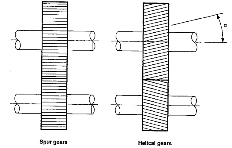
Of the various types of gears used in engineering, the most common are spur and helical gears. These are illustrated in Figure 2.
Spur gears have the teeth cur parallel to the axis of the shaft
Helical gears have the teeth cut at an angle to the axis of the shaft. The angle is called the helix angle, $ \alpha $ and is usually about 20° for single helical gears or about 30-35° for double helical (herringbone) gears.
Note: With a helical gear pair, one helix must be right-hand and the other left-hand.
Velocity Ratio
For all gears other than the worm and wheel, the velocity ratio of a gear pair is the ratio of the number of teeth in each gear. For example, if a 20 tooth pinion meshes with a 40 tooth wheel, the velocity ratio is:
$$ VR = \frac{40}{20} = 2 $$In the case of a compound gear train, the overall velocity ratio is the multiplication of the velocity ratio of each gear pair. If in the above example, the wheel had a 20 tooth pinion attached to it, that meshed with a 60 tooth wheel, the overall velocity ratio is:
$$ VR = \frac{40}{20} \times \frac{60}{20} = 2 \times 3 = 6 $$In the case of a worm and wheel, the velocity ratio is the number of teeth in the wheel divided by the number of starts in the worm. So if a 12 start worm meshed with a 61 tooth wheel, the velocity ratio is:
$$ VR = \frac{61}{12} = 5.083 $$Number of teeth
It is impractical to have gears with too few teeth (just try and draw a gear with say 3 teeth). To get a reasonable tooth profile without undercutting and with a smooth transfer of power from pinion to wheel, a rule-of-thumb is that spur gears should have at least 17 teeth on the pinion and helical gears (20° helix angle) should have at least 14 teeth on the pinion.
For maximum life with meshing gears it is desirable to distribute the wear uniformly amongst all teeth, that is not to have the same teeth in mesh for every revolution of the wheel. The best situation possible is that the same teeth mesh together again only after the pinion revolutions equals the number of teeth in the wheel. This is also known as having all the teeth hunting. For example if there are 40 teeth in the wheel, the best possible situation is that re-meshing of the same teeth occurs only after the pinion has made 40 revolutions. The condition for this is that the velocity ratio cannot be reduced to a simpler ratio, that is, there is no common factor between the number of teeth in the pinion and the number of teeth in the gear.
Some possible combinations are given in Table 1:
| Teeth in Pinion | Teeth in Wheel | Revolutions of the pinion when cycle repeats |
|---|---|---|
| 18 | 38 | 19 |
| 19 | 38 | 2 |
| 20 | 38 | 19 |
| 21 | 38 | 38 |
| 18 | 40 | 20 |
| 19 | 40 | 20 |
| 20 | 40 | 2 |
| 21 | 40 | 40 |
It can be seen therefore, that there can be a huge difference in the way wear will be distributed for approximately the same velocity ratio. However, in practice, exact velocity ratios are often needed (for example, for a camshaft) and in such cases, hunting teeth cannot be provided.
Limiting velocity ratio
For a worm-wheel gear pair, the smallest velocity ratio obtainable in practice is about 5. For all other gear pairs, the smallest ratio is 1. There is no theoretical upper limit to the velocity ratio, however high velocity ratios are undesirable because of the large number of teeth that need to be cut in the wheel. This makes accurate machining difficult (if not impossible) and requires large centre distances which are also not usually desirable.
For example, consider a velocity ratio of 125 obtained with single pair of spur gears. With a pinion of 17 teeth and PCD 17 mm, the wheel would require 2125 teeth and a PCD of 2125 mm! The total number of teeth to be cut is 2142!
The same velocity ratio can be obtained with a compound gear train with 3 pairs of gears in mesh, each with a velocity ratio of 5. Then the total number of teeth that need to be cut is 306 (7 times less) and the maximum wheel PCD is only 85 mm.
Rule-of-thumb limits for a gear pair are given in Table 2 :
| Type of gear pair | VR lower limit | VR upper limit |
|---|---|---|
| Worm and wheel | 5 | 60 |
| All others | 1 | 5 |
Efficiency
The efficiency of a gear pair depends upon a number of factors:
- Accuracy and finish. The better this is the higher the efficiency. In most cases, gears are accurately cut and machined to a fine finish. However in some cases gears may be cast and not machined.
- Bearings used to support the gear shafts. The lower the bearing friction, the higher the efficiency. In most cases, rolling-element bearings are used.
- Lubrication of the gears and bearings. The better the lubrication, the higher the efficiency. In most cases the gears are oil-lubricated but pre-sealed rolling-element bearings are also used.
With well machined and lubricated gears supported by rolling element bearings, the efficiency is usually about 95-96% for each gear pair. With a gear train, the overall efficiency is approximately the product of the efficiency of each gear pair. For example with a three pair compound gear train, if each pair has an efficiency of 96%, the overall efficiency will be about $0.96 \times 0.96 \times 0.96 = 0.885$.
Gear Parameters
Consider two gears in mesh as shown in Figure 3:

If the pinion has $n$ teeth and $PCD = d$ , and the wheel has $N$ teeth and $PCD = D$ then:
$$VR = \frac{N}{n} = \frac{D}{d}$$The nominal centre distance $C$ is:
$$ C = 0.5 (d + D) $$This is known as the nominal centre distance because the actual centre distance is usually somewhat greater than this.
The height of a tooth above the PCD line is known as the addendum A. The height of a tooth below the PCD line is known as the dedendum B.
The angle made by the tangent to the gears at the point of contact is called the pressure angle $\theta$. This angle is usually 20° and should be assumed so unless otherwise stated.
The point of contact is called the pitch point P. In order to obtain a constant velocity ratio the pitch point should not move as the gears move into and out of mesh. If the pitch point did move in and out with each mesh, then this would cause acceleration/deceleration with each mesh. If the gears are rotating at relatively high speeds this would cause high acceleration/deceleration with high inertia forces and accelerated wear.
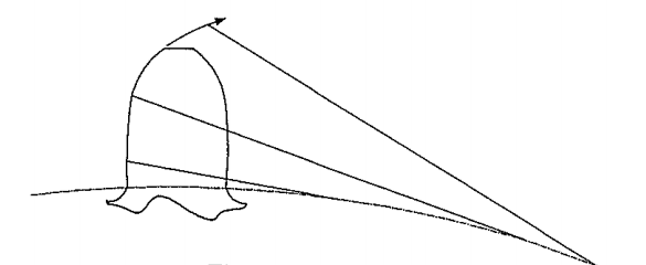
The pitch point remains fixed when the gears are cut with an involute profile. The involute profile can best be demonstrated by unwinding a thin cord from around a cylinder as shown in Figure 4.
In the case of a rack and pinion, the mating profile to the involute on the pinion is a straight sided rack as illustrated in Figure 5. The angle of the rack is the pressure angle as previously defined.

Clearence
To minimise friction, the teeth should contact only along the front face of the driver and the back face of the driven. There should be both circumferential and radial clearance as shown in Figure 6.

Radial clearance (or bottom clearance) is obtained by making the dedendum greater than the addendum. Usually $B = 1.25A$. Circumferential clearance is usually very small when the gears are new because wear automatically increases it. It can be obtained by making the centre distance slightly larger than the nominal centre distance. Circumferential clearance causes backlash and can be measured by holding one gear fixed and moving the other gear back and forth relative to it.
Module $M$
Module M One of the most important parameters in gear design is the module which may be defined as the pitch circle diameter divided by the number of teeth. For a gear pair, the module must be the same for pinion and wheel. Hence:
$$ M = \frac{d}{n} = \frac{D}{N} $$Standard modules (first choice) in mm are:
1 1.25 1.5 2 2.5 3 4 5 6 8 10 12 16 20 25 32 40 50
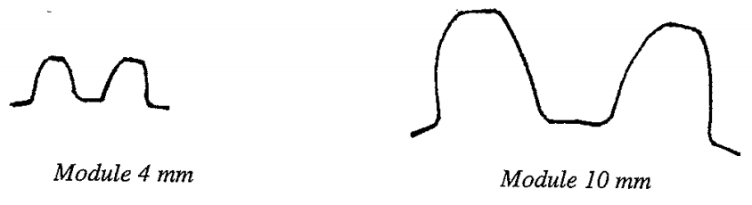
As the module increases, thedize of the gear teeth increase. That is, the gears become stronger and can transmit more torque and power. For example with a PCD of 200 mm, a module of 1 mm would mean 200 small teeth whereas a module of 10 mm would mean 20 large teeth. This is illustrated in Figure 7.
The addendum, dedendum and depth of gear teeth are directly related to the module. For gear teeth of standard proportions the following relationships apply:
- Addendum $A = M$
- Dedendum $B = 1.25M$
- Tooth depth $= A + B = 2.25M$
The face width of gears is also related to the module but is also dependent upon the gear load (torque). The following rule-of-thumb face widths $W$ of the wheel are usual in mechanical power transmission:
- Relatively light loads $W = 8M$
- Moderate loads $W = 10M$
- Heavy loads $W = 12M$
Note: The face width of the pinion is usually 5-10% larger than the wheel (depending upon assembly tolerances).
Example 1
A spur gear pair are to have a velocity reduction ratio in the range 2.5 to 2.7. The proposed number of teeth in the pinion is 18 with a module of 5mm. Determine:
- A suitable number of teeth in the wheel and the reduction ratio in order to have all hunting teeth,
- PCD of pinion and wheel,
- Nominal centre distance,
- Addendum, dedendum and tooth depth,
- Face wisth of pinion and wheel if loads can be described as moderate.
Solution
a)
Various combination of teeth in the wheel, velocity ratio and revolutions of the pinion when the cycle repeats are set out in the table below:
| Teeth in pinion | Teeth in wheel | Velocity ratio | Pinion revolution when cycle repeats |
|---|---|---|---|
| 18 | 45 | 2.5 | 5 |
| 18 | 46 | 2.556 | 23 |
| 18 | 47 | 2.611 | 47 |
| 18 | 48 | 2.667 | 8 |
Hence it is seen that the only combination that give a velocity ratio in the required range with all teeth hunting is the 18:47 ratio. Hence choose 47 teeth in the wheel with velocity ratio 2.556.
b)
PCD of the pinion $= 5 \times 18 = 90mm $
PCD of the wheel $= 5 \times 47 = 235mm $
c)
Nominal centre distance $C=0.5(d+D)=0.5\times(90+235)=162.5mm$
d)
Addendum $A = M = 5mm$
Dedendum $B=1.25M=6.35mm$
Tooth depth $=A+B=11.25mm$
e)
For moderate loading assume face width of the wheel $W=10$ $M=50mm$
Face width of the pinion, say 7% larger $= 1.07\times50=53.5mm$
Gear design
A comprehensive design procedure for gears is very complex and outside the scope of this manual. For example, AS2938 - Gears - Spur and Helical - Guide to Specification and Rating lists 88 different variables and constants and contains 32 different charts!
The most important factor to determine when designing gears for a certain application is the module. As has been stated, the greater the loading, the larger the size of the gear teeth and the larger the module.
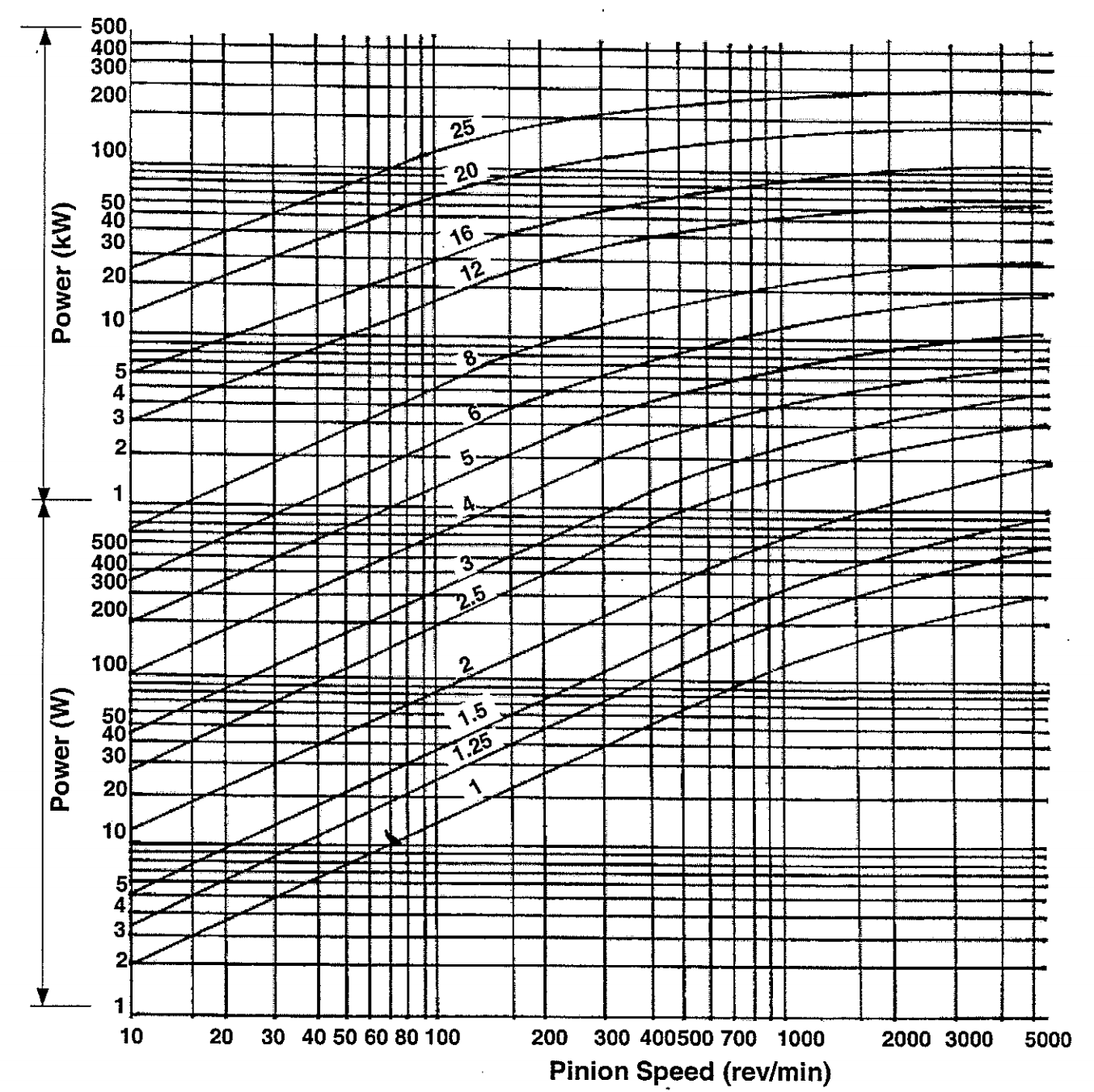
A simplified factor to module selection is the use of a chart as the one given as Figure 8. This chart has been drawn for spur gears with face widths = 10M and with 18 teeth in the pinion. It may be used for face widths in the range 8-12M and for pinions with 17-19 teeth. It may also be used for helical angles up to 20°. However, because helical gears are inherently stronger than spur gears, a somewhat smaller module will be satisfactory (say one standard size down).
Example 2
A helical pinion transmits 20kW @ 1500 rev/min to a mating gear. Loading is moderate. Determine suitable values for:
- The module for pinion and gear;
- The face width of the pinion and the gear;
- The PCD of the pinion.
Solution
a)
From Figure 8, the module lies between 6 and 8. A module of 7 is not standard (first choice). Because the gear is a helical one, the choice of the smaller module is justified. Hence choose $M = 6$.
b)
With $M = 6$ and face width of the gear $= 10M$ (moderate loading), therefore the face width of the gear = 60 mm.
For the pinion, make the face width about 7% larger, say 64mm.
c)
Make the number of teeth on the pinion = 19.
Then the pinion $PCD = 6 \times 19 = 144mm$.
Gear tooth forces
The forces acting on gears in mesh occurs at the point of contact of the gears (the pitch point). The force $F$ as shown in Figure 9.
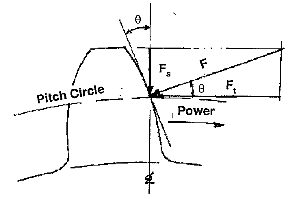
In this diagram:
- $F=$
- resultant transverse force on the tooth at the pitch point. This is also the resultant transverse load on the shaft at the location of the gear. Note that this force acts perpendicular to the tooth at the pitch point.
- $F_s=$
- separating (or radial) force on the tooth at the pitch point. Its line of action passes through the centrelines of the two gears. This force is needed to keep the gears together and without it, the gears would simply slip out of mesh and not transmit any torque.
- $F_t=$
- tangential force acting on the tooth at the pitch point. This force multiplied by the pitch circle radius gives the torque transmitted by the gear.
- $\theta=$
- the pressure angle, that is the angle between forces $F$ and $F_t$. For most gears, this angle is 20° and should be assumed so unless otherwise stated.
Spur gear forces
Because torque is the tangential force multiplied by the pitch circle radius it is clear that the tangential force on the gear is calculated by:
$$ F_t = \frac{2T}{d} $$Where $T=$ torque Nm and $d = PCD$ of the gear in m.
From Figure 9,
Separating force on spur gear
$$ F_s = F_t\tan\theta $$and the resultant transverse force on the gear
$$ F = \sqrt{F_t^2 + F_s^2} $$Helical gear forces
Because the teeth are cut at an anlge (the helix angle), there is also an axial force on the gears. Te tangential force is the same as for the spur gears but the formula for the separating force becomes:
$$ F_s = \frac{F_t\tan\theta}{\cos\alpha} $$Where $\alpha$ is the helix angle.
The axial force on the gear given by:
$$ F_a = F_t\tan\alpha $$Example 3
A spur gear PCD 100mm transmist 800Nm of torque. Determine the tangential, separating and resultant force on each gear.
Solution
The tangential force is:
$$ F_t = \frac{2T}{d} = \frac{2 \times 800}{0.1} = 16kN $$The separating force is (assuming a pressure angle of 20°):
$$ F_s = F_t\tan\alpha = 16\tan20 = 5.82kN$$The resultant force is:
$$ F = \sqrt{F_t^2+F_s^2} = \sqrt{16^2+5.82^2} = 17kN $$Example 4
Repeat Example 3 for helical gears with helix angle 20° (all other data being the same). Also calculate the axial force.
$$ F_t = \frac{2T}{d} = \frac{2\times800}{0.1} = 16kN $$ $$ F_s = \frac{F_t\tan\theta}{\cos\alpha} = \frac{16\tan20}{\cos20} = 6.2kN $$ $$ F = \sqrt{F_t^2+F_s^2} = \sqrt{16^2+6.2^2} = 17.2kN $$ $$ F_a = f_t\tan\alpha = 16\tan20 = 5.82kN $$Additional Information & Resources
This section contains the slides and a set of links to some useful resources that will help you form your PDS.
Lecture Slides
- Lecture 1:
- Introduction to the Exercise
- Lecture 2:
- Product Design Specification, Concept Design & Selection
- Lecture 3:
- Modelling the Deployment of the Mechanism 1
- Lecture 4:
- Modelling the Deployment of the Mechanism 2
- Lecture 5:
- Gearbox Design
- Lecture 6:
- Submission Details
- Session 1:
- Slides
- Session 2:
- Slides
- Session 3:
- Slides
- Session 4:
- Slides
- Session 5:
- Slides
- Session 6:
- Slides
Useful Links
- Bosch Motors (Select your motor from here!)
- Linkage Software
- Report Template
- Simulink Templates
- Convertible Roof Retraction Times
- BMW 318i Convertible Motor
- BMW Convertible Top Damper
- Convetible Damper for Convertible Roofs
- Oil Hydraulic Dampers
- Slam Proof Dampers
- Folding an A3 page into an A4 Report
- Porsche Electric Roof Repair
- Teeth Hunting
- Gear Catalogue (Note: you do not have to select gears, this is for interest only)
- Spur Gears
- Helical Gears
- Worm & Spiral